The stability of the tundish in continuous casting is a prerequisite for ensuring stable production and good billet quality. A long-life tundish reduces the frequency of tundish replacements, thus reducing labor intensity for workers and decreasing the occurrence of production accidents. Therefore, extending the tundish’s lifespan has become a focus of production and quality pursuits.
In actual production, many factors limit the tundish’s lifespan, among which the phenomenon of steel jamming at the sizing nozzle is frequent and has become a common factor restricting its lifespan. First, jammed sizing nozzles cannot be replaced, reducing the tundish’s lifespan and increasing production costs. Second, severe steel jamming at the sizing nozzle can even lead to steel drilling accidents. Therefore, solving the problem of steel jamming at the tundish sizing nozzle is essential from both cost and safety perspectives.
1.Structure and steel clamping condition of sizing nozzle
(1) Continuous casting tundish sizing nozzles are divided into two types: “quick-change type” and “swing-handle type”.
The “quick-change type” mechanism consists of a machine base, fixed slide, spring-loaded movable slide, lower sizing nozzle bracket, and spring guard plate. The refractory material part consists of the upper nozzle seat brick, upper nozzle, upper sizing nozzle, and lower sizing nozzle.
The “swing-handle type” mechanism consists of a machine base and a reversing fan-shaped plate. The refractory material part consists of the upper nozzle seat brick, upper nozzle, upper sizing nozzle, lower sizing nozzle, and transition block.
The working principle and influencing factors differ slightly depending on the structure of the sizing nozzle.
(2) The fundamental cause and condition of steel clamping in sizing nozzles.
The fundamental cause of steel clamping in sizing nozzles is an excessively large gap between the plates (generally, the gap between sizing nozzles should be ≤0.3mm) or severe “pitting” erosion of the sizing nozzle, as shown in Figure 1. Analysis of the erosion and steel-clamping condition of the sizing nozzles on site indicates that the “pit damage” phenomenon of the sizing nozzles is the origin of the erosion and steel-clamping of the sizing nozzles.
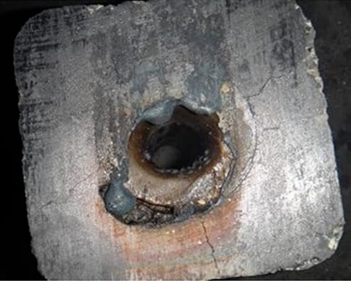
For example, factors such as misalignment of the upper and lower sizing nozzles during use, artificial flow control during casting, or severe erosion of the upper nozzle during expansion can all lead to misalignment of the upper and lower sizing nozzles, exacerbating erosion of the inner wall of the lower nozzle and creating a “damage pit” phenomenon in the gap between the inner diameter plates. When replacing the nozzle in this situation, the molten steel carried within the “damage pit” will be forced into the gap of the sizing nozzle during high-speed sliding or oscillating motion, resulting in steel clamping.
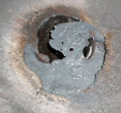
Generally, the thickness of the steel sheet causing steel clamping in sizing nozzles is ≤1mm, and the area varies, with the largest potentially covering the entire outer edge of the zirconium core of the sizing nozzle, as shown in Figure 2. Once steel clamping is detected in the sizing nozzle during production, the replacement operation must be stopped immediately to prevent “blank leakage” (steel leakage from the tundish).
2.Analysis of influencing factors and practical reasons
2.1 Refractory Material Factors
The sizing nozzles used in continuous casting are generally made of alumina-carbon refractory material, with an internal zirconium core to enhance corrosion resistance. The main component of the zirconium core is ZrO2, with the addition of small amounts of stabilizers (CaO, MgO, etc.).
During use, the sizing nozzle reacts with impurities in the molten steel (MnO2, SiO2, MgO, Al2O3, etc.) to form multi-component low-melting-point oxides, which are lost with the molten steel, causing erosion and diameter expansion of the nozzle. In addition, the sizing nozzle suffers severe burn-off, erosion, and diameter expansion during oxygen diversion or molten steel throttling.
The rationality of the production and design of the sizing nozzle is also an important factor affecting its use. A common sizing nozzle process flow is: batching → premixing → mixing → forming → drying → firing → sorting → bonding and assembly → surface coating with slip oil. Strict adherence to standards at each process stage ensures the production of qualified products.
The design of sizing nozzles typically features a streamlined, flared upper end. During operation, this design directs molten steel into the lower sizing section. This primarily aims to reduce resistance and agitation of the molten steel within the nozzle, improving the product’s erosion resistance. This also reduces the likelihood of steel inclusions due to gaps in the sizing nozzle.
Determining the nozzle diameter is a crucial factor in its design. An empirical formula for designing the nozzle’s inner diameter D is shown in (1):
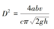
In the formula: D – diameter of the sizing nozzle in the tundish, mm; a, b – width and thickness of the cross-section of the crystallizer, mm; v – continuous casting speed, m/min; c – coefficient, c=λβ; g – gravitational acceleration, m/s²; h – height of the molten steel level in the tundish, mm.
Besides the design of the sizing nozzle dimensions, actual production factors also have a significant impact on refractory materials. During use, the nozzle must withstand very high temperatures from the molten steel. Initially, the nozzle heats up rapidly, resulting in uneven heating inside the nozzle and subjecting it to severe thermal shock from the molten steel. This leads to thermal stress concentration in the nozzle, and these areas of thermal stress concentration are the source of cracks and melting in the refractory material.
2.2 Mechanism Factors
The “quick-change” mechanism’s slide, sizing nozzle bracket, and base plate must be kept flat. First, ensure that the entire mechanism is free from deformation. Second, ensure that the gap between sizing nozzles meets the requirements (gap between sizing nozzles ≤ 0.3mm). Its upper and lower sizing nozzles are primarily clamped by a movable slide spring system. Therefore, the maintenance standards for the springs must be high, ensuring consistent free height to guarantee balanced force distribution on the movable slide.
According to empirical formula (2):
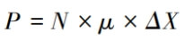
In the formula: P – the surface pressure provided by the sizing nozzle mechanism to the sizing nozzle; N – the number of surface pressure springs; μ – the spring constant of the surface pressure springs; ΔX – the compression of the springs during operation; If the surface pressure springs cannot generate sufficient surface pressure, it may lead to an increase in the gap between the sizing nozzles, resulting in steel clamping.
Furthermore, when replacing the sizing nozzle, a spare sizing nozzle is moved to the working position using a hydraulic cylinder. Therefore, the dimensions of the sizing nozzle bracket and the stroke accuracy of the hydraulic cylinder are crucial control factors to ensure the alignment of the upper and lower sizing nozzles and prevent abnormal corrosion. During the entire process of replacing the sizing nozzle, if the slide is uneven or the force on the moving slide is uneven, gaps may appear in the sizing nozzle, resulting in steel clamping.
The swing-handle mechanism achieves the clamping of the upper and lower sizing nozzles by adjusting the top screw to press the swing groove. During the swinging process of changing the sizing nozzle, the fan-shaped plate swing groove and the base plate of the mechanism must remain parallel and there should be no deformation. This ensures that no gaps are generated in the sizing nozzle during the swinging process, thereby avoiding the phenomenon of steel being clamped in the sizing nozzle.
2.3 Production Process Factors
During production, factors such as excessively high steel temperature and steel fittings cause frequent replacement of sizing nozzles, which greatly affects their lifespan. The deoxidation process of the steel also has an impact. Reference [4] points out that calcium treatment causes some melting loss to the sizing nozzle, which can only be addressed by considering the material of the sizing nozzle. Besides the influence of steel factors, there are also human error issues in the process of replacing sizing nozzles in continuous casting. For example, during the opening of the ladle for oxygen injection in continuous casting, deviations in human operation can cause severe burning of the sizing nozzle, increasing the probability of steel clamping. During the replacement of sizing nozzles, foreign objects may remain in the slide of the “quick-change” sizing nozzle and may not be cleaned properly; uneven force may be applied during the swinging process of the “swing handle” sizing nozzle. These are all human factors that cause gaps in the sizing nozzle, leading to steel clamping.
3.Measures to prevent steel from being sandwiched in the sizing nozzle of the tundish
(1) Before installing the machine parts, clean the base plate thoroughly, especially removing any cold steel. Verify that the machine parts and base plate are in good condition before installation.
Before installing the sizing nozzle, check that the plate surface is flat and free of cracks and damage. After installing the sizing nozzle, adjust the clamping device to ensure the sizing nozzle gap meets the standard (gap between sizing nozzles ≤ 0.3mm).
After the entire mechanism is installed, perform a replacement operation inspection to check the smoothness of the replacement process. Accurately measure the sliding stroke of the sizing nozzle to ensure the alignment of the upper and lower sizing nozzles.
(2) The converter provides qualified molten steel for continuous casting. Improving the sizing nozzle replacement technique in continuous casting and reducing abnormal erosion of the sizing nozzles caused by human error are crucial. Special attention should be paid during production to ensure that foreign objects are thoroughly cleaned from the slideway and swing trough.
These are all effective measures to prevent steel clamping at the sizing nozzle during production.
4.Summarize
(1) Ensure the sliding mechanism of the sizing nozzle in continuous casting is free from deformation, that there are no foreign objects along the sliding stroke of the sizing nozzle, and that the gap between sizing nozzles is ≤0.3mm.
(2) Ensure the sizing nozzle dimensions are reasonably designed, that there are no damages or cracks before use, and that the plate surface is flat and free from unevenness.
(3) Ensure a stable production rhythm, that the molten steel quality is up to standard, and that there are no high or low temperatures or molten steel interception phenomena.
(4) Ensure that personnel replacing sizing nozzles are highly skilled, and that there are no accidental burn-outs or diameter expansions caused by human factors.
In conclusion, a thorough understanding of the working principles of different mechanisms of the sizing nozzles in continuous casting tundish, and the determination of corresponding measures based on different influencing factors, can effectively prevent the problem of steel jamming in the sizing nozzles of continuous casting tundishes.