Structure of the Calcium Carbide Furnace
The calcium carbide furnace is the primary equipment used to produce calcium carbide. Inside the furnace, the high temperatures generated by the electric arc cause the furnace charge to melt and react, producing calcium carbide. Since the reaction temperature exceeds 2,000°C, ordinary refractory materials cannot withstand such high temperatures. Therefore, the furnace volume must be larger than the reaction space. In other words, a layer of furnace charge should be left between the reaction zone and the furnace lining to protect the lining.
Furnace bodies come in many shapes, including circular, elliptical, square, and rectangular. From a thermodynamic perspective, a circular furnace is more advantageous. In practice, the choice of furnace shape is primarily determined by the arrangement of the electrodes and the installation location of the carbon monoxide extraction equipment. Today, the vast majority of calcium carbide furnaces are circular, with other shapes being extremely rare.
The size of the reaction space within the furnace is determined by the size and spacing of the electrodes, as well as the range of the electric arc. The spacing between circular electrodes is directly proportional to their diameter. The electrode diameter, in turn, varies with the furnace capacity. The electrode diameter is further determined by the permissible current density. The current through the electrodes is determined by the transformer capacity. Ultimately, the size of the furnace is determined by the capacity of its transformer.
The selection of the furnace size and the distance between the electrodes is of critical importance. When the dimensions are appropriately chosen, most of the current flows from the electrode tips through the reaction and melting zones to the furnace bottom. Under these conditions, the calcium carbide furnace operates very smoothly. Otherwise, a large portion of the current flows from one electrode through the material diffusion zone and the preheating zone to the other electrode. Consequently, the electrodes cannot penetrate deeply into the furnace, the furnace bottom temperature drops, the three-phase flow within the furnace becomes obstructed, calcium carbide discharge is hindered, furnace operation deteriorates, and production is severely compromised. Guided by Chairman Mao—the leader of the Chinese working class—and his teachings of “independence and self-reliance,” and through more than two decades of practical experience, we have essentially identified this principle, thereby creating extremely favorable conditions for the future development of China’s calcium carbide industry.
Structure of the Calcium Carbide Furnace Body and Furnace Door
(1) Furnace Shell
Requirements for the furnace shell: ① The strength of the furnace body must be sufficient to accommodate the severe expansion of the furnace lining caused by heat and to withstand the thermal expansion and contraction of the lining; ② While meeting strength requirements, efforts should be made to conserve materials and reduce weight; ③ The design should facilitate manufacturing, and the feasibility of packaging and transportation should be considered when necessary.
Currently, there are two structural types of furnace shells used domestically: one is the cylindrical shell, which is adopted by most calcium carbide plants. The other is the inverted conical furnace shell, with a cone angle of 7°. This type of furnace shell has only recently begun to be adopted in China.
Structurally, the inverted conical furnace shell is simpler, requiring fewer horizontal and vertical stiffeners, which saves steel. However, its fabrication and on-site assembly are more complicated. From a developmental perspective, the inverted conical furnace shell holds promise for the future.
The furnace shell is made of steel plates with a thickness of 8 to 12 millimeters. The furnace walls and bottom are divided into two sections and connected with bolts.
(2) Filling Layer
Typically, furnace lining bricks are laid using the wet method. Since they expand when heated, a layer of asbestos board (or slag wool or dry sand) must be placed between the refractory bricks and the steel shell. This layer is called the filling layer, also known as the buffer layer. Its thickness depends on the furnace size, the laying method, and the properties of the refractory materials, and is generally between 50 and 100 millimeters.
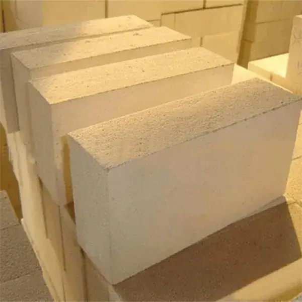
(3) Refractory Brick Lining:
Six layers of refractory bricks are laid on top of the filling layer, with a total thickness of approximately 450–500 mm. The furnace walls are lined with two layers of refractory bricks extending up to the furnace roof. Clay refractory bricks are generally used, and there are two methods for laying them: dry laying and wet laying. The wet-laying method uses a mixture of 70% fired refractory powder and 30% raw refractory powder, blended with water. Joint widths must not exceed 3 millimeters. The dry-laying method is technically more demanding; therefore, it is commonly used for large-capacity calcium carbide furnaces, while the furnace walls are constructed using the wet-laying method.
In large-capacity calcium carbide furnaces, during discharge, the high flow rate of calcium carbide per unit time causes severe thermal corrosion of the lining near the discharge opening. Therefore, corundum bricks are used for the lining in this area. The technical specifications for corundum bricks are as follows: 92% alumina, refractoriness of 1880°C, load-bearing softening point of 1690°C or higher, and compressive strength of 1078 kg/cm².
(4) Carbon Brick Lining:
Carbon bricks are laid on top of the refractory brick layer. The thickness of the carbon brick layer varies depending on the capacity of the calcium carbide furnace: 400–800 mm for small-capacity furnaces, 800–1,200 mm for medium-capacity furnaces, and 1,200–1,500 mm for large-capacity furnaces. There are two methods for laying the carbon brick layer: the wide-joint method and the narrow-joint method. The wide-joint method involves leaving a 30–50 mm gap between bricks. A paste made from wide-joint mortar is heated until it reaches a paste-like consistency, then filled into the gaps between the bricks. It is subsequently compacted using specialized tools and pneumatic tools operating at a pressure of 3–7 kg/cm². The joints between the upper and lower layers must be staggered. A layer of coarse joint mortar 50–100 mm thick must also be applied between the carbon bricks and the refractory bricks, between the carbon bricks themselves, and on the top surface of the carbon brick layer. The fine-joint method involves machining the carbon bricks on a planer to achieve a high-precision flat surface. They are pre-assembled at the factory, with a dimensional tolerance of ±1 mm required for each carbon brick. When constructing a calcium carbide furnace, the joints between bricks are filled with molten fine-joint mortar, with a required joint width of no more than 2 mm. Of these two methods, the fine-joint method is superior. However, due to the significant amount of machining required, this method is generally used only in large-capacity calcium carbide furnaces. The coarse-joint method is easier to implement, but because volatiles evaporate during production, voids can easily form in the joints, resulting in poor resistance to ferrosilicon penetration. Most medium- and small-sized calcium carbide furnaces use this method. Currently, carbon bricks supplied by carbon factories in China are sized at 400 × 400 × 2,500 mm, making them suitable for use in Chinese calcium carbide plants.
In large-capacity calcium carbide furnaces, the lower section of the furnace wall lining is also constructed using carbon bricks. This layer of carbon bricks is filled with fine-joint mortar between it and the furnace bottom bricks. The carbon bricks are approximately 900 mm high and 400 mm thick. Corundum bricks are used near the furnace door to prevent oxidation of the carbon bricks.
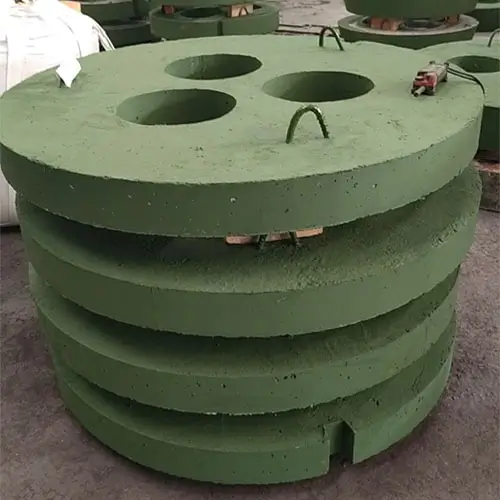
Structure of the Furnace Lid in a Sealed Calcium Carbide Furnace
The furnace lid is a critical component that determines the efficiency of gas (CO) collection in a sealed furnace; the effectiveness of the seal is also determined by the structural design of the furnace lid and related components.
Requirements for the furnace lid: ① It must be capable of operating under high-temperature conditions (typically 400–600°C, with instantaneous peaks of 1100–1200°C) and under the impact of high-temperature furnace gas. ② It must have a certain arch height and minimize heat loss. ③ It must allow for easy removal of the electrode head after the electrode breaks. ④ Due to the numerous openings in the furnace cover, it must possess sufficient strength and ensure good sealing and insulation with the furnace body, electrode holder, and feed pipe. ⑤ It must have a long service life, be easy to manufacture, and be convenient to replace.
Currently, the furnace cover types used in China’s sealed calcium carbide furnaces are basically the following four:
① All-refractory concrete structure;
② Water-cooled metal frame with refractory concrete lining;
③ All-metal structure with water cooling;
④ Metal frame with water cooling and refractory brick lining;
The first type is a fully refractory concrete furnace cover. Although this type of cover has a simple structure, low heat loss, and requires less magnetic-resistant steel, it has poor resistance to sudden temperature changes and the mechanical erosion of furnace gases. Furthermore, at high temperatures, it develops cracks and delamination, sometimes causing the material to peel off in layers, fall into the furnace, and form hard lumps, thereby affecting production. Currently, this type of cover is rarely used in calcium carbide furnaces.
The second type is a water-cooled metal-framed refractory concrete furnace cover. While the water-cooled metal frame of this cover is a sound design, the refractory concrete lining is prone to deformation and spalling. Although some plants are currently using this type of cover, its performance remains less than ideal.
The third type is a water-cooled all-metal structure furnace cover. Although this type of cover has high mechanical strength, it cannot be manufactured as a single unit and must be divided into at least three sections, making it difficult to achieve a tight seal between the sections. Consequently, during production, the furnace cover is prone to smoke and flame emissions. Additionally, it suffers from significant heat loss, requires a large amount of steel, and presents challenges in handling the insulation layer. This type of cover is also not ideal.
The fourth type is a water-cooled metal-framed furnace cover lined with refractory bricks. This design is structurally sound. By lining the metal frame with arched refractory bricks, it not only minimizes heat loss but also offers high mechanical strength, making it resistant to detachment. Sealing and insulation are also handled effectively. This type of furnace cover shows great potential for future development.