
In a steelmaking plant, the ladle serves to transport molten steel from the converter to the continuous casting unit. Positioned on the ladle turret, the ladle discharges molten steel—at temperatures of 1,500°C—through a nozzle and slide gate assembly at its base into the tundish. After a brief holding period in the tundish, the steel flows through the tundish nozzle to the continuous casting machine for strand formation. The ladle nozzle itself is housed within a nozzle well block; while the nozzle can be replaced online after 20–25 heats, the well block must be replaced during minor ladle repairs or when the ladle bottom is renewed. The quality of the well block and the standard of its installation directly impact the ladle’s operational reliability. Common issues encountered with ladle nozzle well blocks include material instability, flaws in the ramming process, inadequate preheating, and installation defects. This paper analyzes the problems observed with well blocks on-site and outlines the solutions implemented, ultimately achieving satisfactory results and ensuring the normal operation of the ladles.
On-site conditions of ladle usage
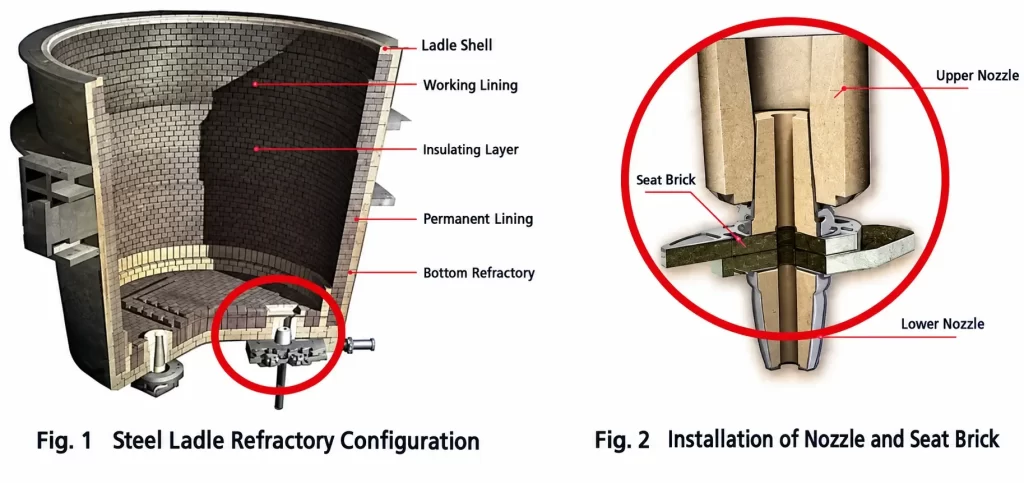
A steelmaking plant utilizes 150-ton ladles equipped with a dual-nozzle system, where the nozzles are embedded directly into the seating blocks; these seating blocks are installed in the ladle bottom during the lining process (using magnesia-carbon bricks) and share the same service life as the bottom lining—typically 70 to 80 heats—while the total service life of the ladle ranges from 130 to 150 heats (a schematic of the ladle’s refractory lining is shown in Figure 1). The nozzles are installed after the ladle preheating process and prior to the ladle entering service; sealing paste is applied to the exterior of the nozzle, and the nozzle is manually pressed firmly into the seating block, creating a tightly integrated assembly of seating block, paste, and nozzle that enhances overall structural strength.
During operation, the uppermost part of the seating block is subjected to the initial impact of molten steel and continuous scouring and erosion as the steel flows out, causing the block’s length to gradually decrease. The nozzle housed within the seating block serves as the direct channel for the outflowing steel, enduring the impact and friction of high-temperature molten steel as well as thermal fluctuations during production; the connection between the nozzle and the seating block is sealed with refractory paste. Between July and September 2019, cracking in the nozzle-seating block assembly occurred repeatedly. Timely detection allowed for the unit to be taken offline; however, delayed detection resulted in molten steel leaking through the paste interface between the nozzle and the seating block—leading to breakouts—which severely disrupted production schedules, increased ladle costs, and placed operations in a difficult, reactive position.
To address the incident of steel leakage occurring between the well block channel and the nozzle due to cracks in the well block, a comprehensive analysis was conducted covering factors such as nozzle quality and composition, well block quality, and installation practices. Inspections confirmed the nozzles were intact, effectively ruling them out as the cause. Regarding the cracked well blocks, the analysis indicated that the cracking compromised structural integrity and reduced strength; this widened the gap between the well block and the nozzle, allowing molten steel to penetrate the refractory mortar voids. Consequently, the cohesive strength of the well block-mortar-nozzle assembly was undermined, and the sealing mortar—unable to withstand the intense heat of the molten steel—gradually eroded, leading to steel spurting and leakage.
Measures and plans addressing steel breakouts
Regarding the steel leakage accidents caused by cracking in the seating bricks, personnel from the steelmaking plant and the technical center collaborated with the manufacturer to identify the root causes. Measures taken included having the manufacturer analyze and adjust the brick material composition, while simultaneously sourcing and trialing products from other domestic manufacturers known for high quality and a strong reputation. The details are as follows:
- During on-site use, well blocks from Manufacturer A exhibited micro-cracks and noticeable diameter expansion in the upper section after extended service (approximately 60 heats);
- Upon removal from service, well blocks from Manufacturer B also showed multiple longitudinal micro-cracks; these cracks were distributed at 90-degree intervals around the mid-section of the block (relative to an observer on the ladle hot-repair platform, the cracks did not appear at the corners).
- The ladle service contractor analyzed the well block material, carefully selected high-quality raw materials for the formulation, and adjusted the composition and ratio of internal aggregates and fines; subsequent operational experience showed a gradual reduction in the incidence of cracking. Measures taken regarding installation included: the well block was installed concurrently with the ladle bottom lining; prior to positioning, the steel structure area beneath the block was cleaned and filled, and the surrounding area was filled and vibrated using castable refractory; finally, the assembly underwent drying and preheating before being put into service (see the diagram below):
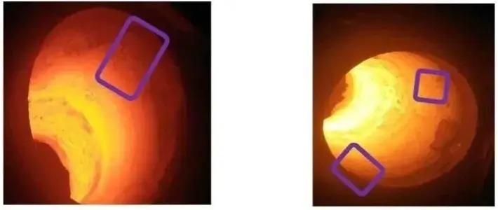
Right image: Cracks in the seating brick from Manufacturer B
- Strictly control the water-to-cement ratio of the castable used around the ladle bottom block, maintaining the moisture content between 6% and 8%.
- Castable installation: Manually vibrate the castable in the gap (30–100 mm) between the bottom block and the ladle bottom; do not use mechanical vibrators, as excessive vibration force could cause the aggregate to settle.
- Inspect the bottom block for cracks and erosion during online nozzle replacement.
- Maintain close communication with the dispatch center; if the waiting time for the ladle to return to service exceeds 30 minutes, a secondary preheating process must be performed.
- Strictly monitor temperatures during ladle preheating using a dedicated logbook to record temperatures at key locations (ladle bottom, sidewall, slag line, and rim), while closely observing venting conditions at the nozzle and sidewall.
- The manufacturer, in collaboration with the company’s technical center, shall produce a comprehensive on-site ladle installation plan for display and conduct regular training sessions.
The result after renovation
Through nearly two months of targeted efforts addressing various aspects of the well blocks, cracking has gradually diminished and disappeared, and service life has been maintained within controllable limits. The modification strategy and its results have been effective, successfully preventing production incidents and reducing refractory material costs.
Steelmaking ladles are crucial tools for the transfer of molten steel; the quality of their internal refractory materials and the standard of their lining installation directly impact the smoothness and safety of production operations. Technical personnel at various steel plants must explore and summarize best practices for the daily management and deployment of these ladles based on their specific operating conditions—insights that are well worth referencing and promoting across the industry.
